How Does Post Processing Work in Metal 3D Printing?
Although the Aerospace and Automotive manufacturing Industry in India is slowly understanding and witnessing the advantages of Metal 3D Printing, there is still a common misconception that Metal 3D Printing is a one-step process.
It is often assumed that once the part is printed, it is ready to use. But in reality, a number of operations are carried out on the printed part to obtain the final functional part. These operations or steps are jointly termed as Post Processing. In this article, we will be concentrating on why each post-processing activity is important and how it is carried out.
Types of Metal 3D Printing
It is well known that Metal 3D Printing produces parts by adding layers of metal on top of one another to obtain the desired shape. Among the different types of Metal Additive Manufacturing technologies available such as Laser Powder Bed Fusion (LPBF), Electron Beam Melting (EBM), Direct Energy Deposition (DED) and Binder Jetting, LPBF is the most widely used technology due to its ability to produce complex parts with better mechanical properties and with consistent quality. So, we shall be specifically considering post-processing of Laser Powder Bed Fusion (DMLS/SLM) parts in this article.
What Happens Before Post Processing?
Before getting into post-processing, let us quickly understand what happens before the stage of Post Processing.
Parts are chosen based on how feasible they are for printing (refer to this blog to understand more on choosing the right part for LPBF). Design changes can be made to make the part more feasible for 3D printing. The 3D model is imported on a data preparation software where the best orientation for printing is set and necessary sacrificial support structures are generated.
The printing parameters are assigned and build simulation is carried out to check part distortion, recoater damage etc. Based on the feedback of build simulation, necessary changes in the data preparation are done and simulated again until the build is ensured to run well. The supports and part is sliced into thin layers of 30 – 90 microns, each layer containing 2D data for the laser beam to move and melt the metal powder. Printing takes place in an inert atmosphere to minimize oxidation.
Steps in Post Processing of DMLS Parts
Once printing is done, the part goes through post-processing activities depending on the end requirement. It is not mandatory for the part to go through all the activities. It is important to understand why each post-processing activity is required and how it is done.
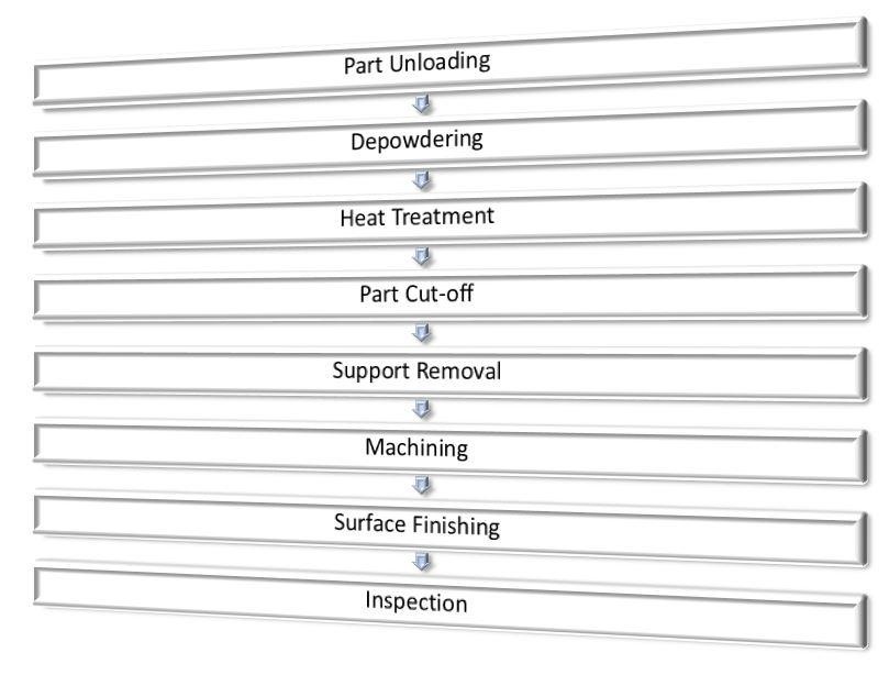
Part Unloading
Once printing is done, the part is surrounded by unmelted powder all around. This unmelted powder is separated from the part and is sieved to remove the condensates and bigger semi-melted particles.
The unloading and sieving process can be done either manually on the machine or through a vacuum powder conveyor module which prevents human contact from the powder.
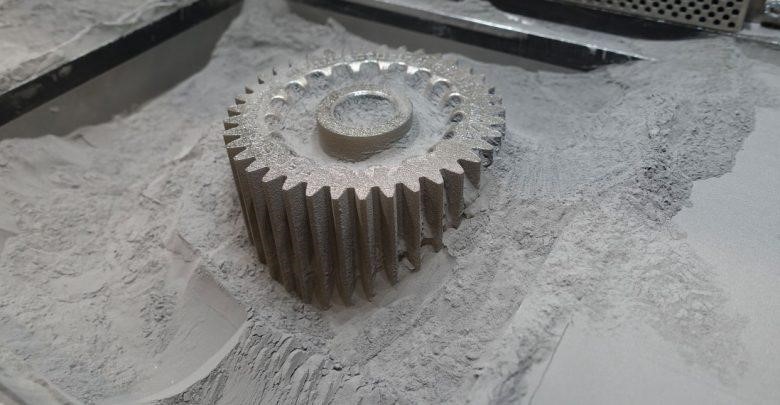
Printed part with unmelted powder around
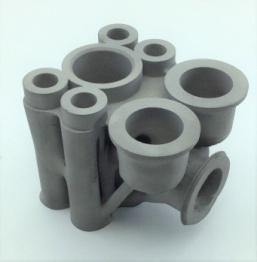
Depowdering
Depowdering is the process of removing trapped metal powder inside the printed part. Mechanical vibration is used to push the powder out of the part.
Image 1 shows an oil injector with internal holes of 0.6mm in diameter. There is a huge possibility of metal powder getting trapped in these channels.
Image 2 shows a conformal cooled tooling insert where the coolant is continuously passed through the channels for heat removal from the die-cast part.
In parts such as these, any trapped powder in the part will hinder the functionality. Also, if the part is subjected to Heat Treatment without depowdering, the powder will solidify which blocks the channels.
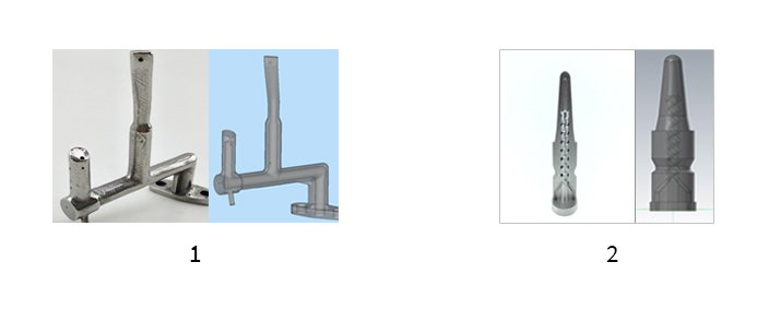
Photo of Internal Channels in 1) Oil Injector 2) Die-Cast Tooling Insert
Heat Treatment
Heat treatment of 3D printed parts is carried out in a vacuum/inert furnace. Depending on the chemical composition of the material, the heat treatment cycle is set. Heat Treatment reduces the internal thermal stresses caused while printing. It also improves the mechanical properties of the printed parts.
It is to be noted that heat treatment is done before separating the parts from the build plate, in order to eliminate warpage of parts.
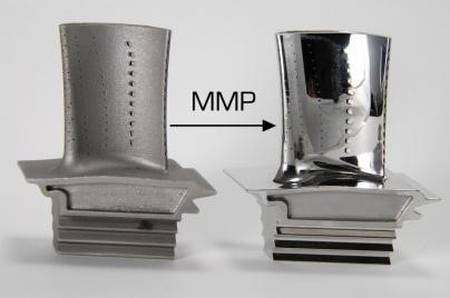
In addition to Heat Treatment, parts can be subjected to Hot Isostatic Pressing (Hipping), wherein high pressure and temperature are applied simultaneously to make the parts much stronger and denser.
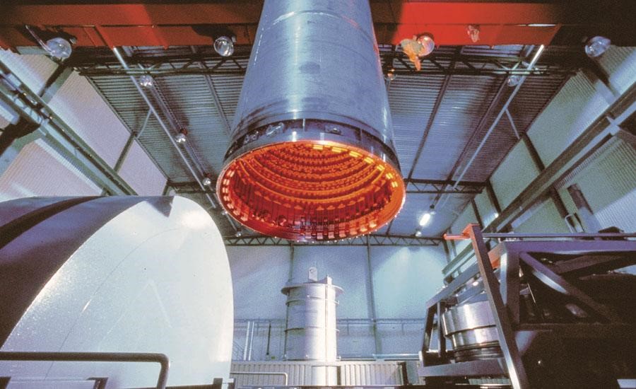
Hipping Facility
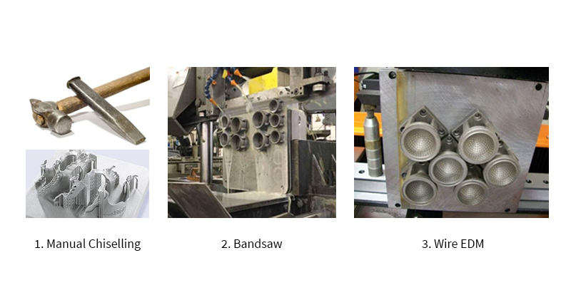
Part Cut off
Once heat treatment is done, the part needs to be cut off from the build plate. Depending on the part and supports, cut-off from the plate can be done by three ways.
1. Manual Chiselling
Only if the supports are weak and minimal, this option can be explored. By chiselling out the supports.
2. Bandsaw
Bandsaw cutting requires extra material around 5mm to be printed to compensate for the blade thickness. This will increase the printing cost for bulky materials. Also, bandsaw is not precision cutting. So the cut surface has to be machined later for a better finish.
3. Wire EDM
Wire EDM is the most easiest and precise method for cut-off. As the parting wire is just 0.2mm in diameter, extra material of just 0.25mm thickness is to be printed to compensate for the wire diameter.
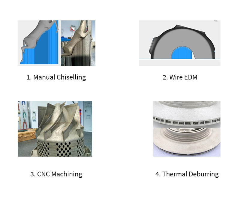
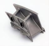
Support Removal
It becomes easier to remove the sacrificial supports once the part is separated from the build plate.
The common method used is manual chiselling of supports. But the part surface to which support is attached needs to be later finished to improve the surface roughness. (Image 1)
For surfaces with 2D profiles having supports beneath and requiring good surface finish, Wire EDM is used to remove the supports. (Image 2)
For complex surfaces having supports beneath and requiring good surface finish, CNC machining is used to remove the supports. (Image 3)
For removing supports that are inaccessible through manual tools or CNC machine tools, thermal deburring is used to make the supports become weak at the teeth which separated the part from supports. (Image 4)
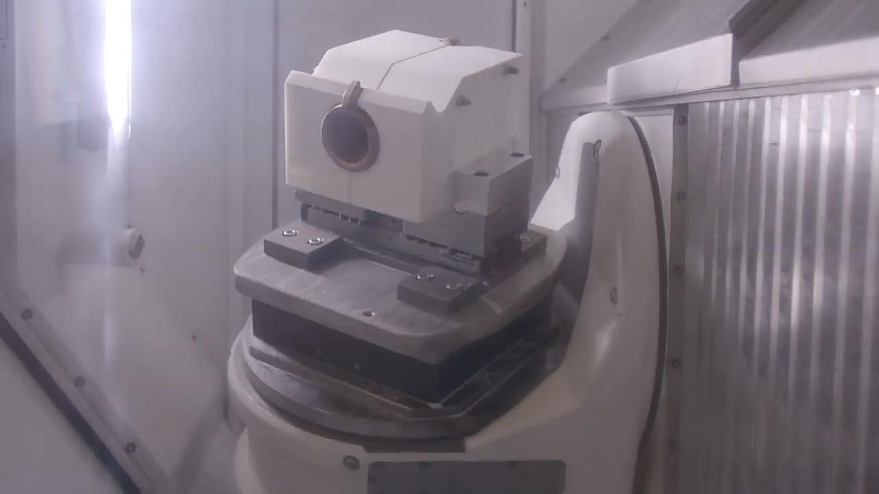
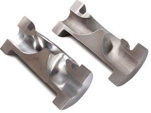
Machining
Quite often, 3D printed parts will need some kind of machining required on them. The features could be threads for fastening, holes for mounting a shaft or a flat surface for butting.
If required, part specific Jigs and Fixtures are manufactured to clamp the part.
1. Mating 3D printed parts after machining
2. A 3D printed part specific fixture to clamp the part during machining
Surface Finishing
Depending on the kind of surface finish and the aesthetic look required, surface finishing technique is selected.
Vibro tumbling, Shot Blasting, Abrasive flow Machining, Plating, Polishing and Micro Machining are few of the surface finishing techniques.
Vibro Tumbling
Shot Blasting
Abrasive Flow Machining
Electropolishing
Micro Machining Process
Inspection
Inspection is the final stage of post-processing. Three types of inspections are carried out.
Dimensional Inspection – To make sure that the dimensions are meeting the GD&T of the 2D drawings. Depending on the dimension, the measuring instrument is selected.
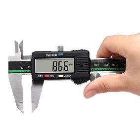
1. Digital Calipers
2. CAD Compare using Laser Scanning
Mechanical Inspection – To make sure that the mechanical properties of the printed part is meeting the values proposed in the material datasheet. Tensile, shear, microstructure, density and hardness tests are carried out to compare the values against the values in the datasheet.
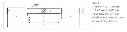
1. Tensile Testing Specimen
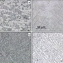
2. Microstructure Report
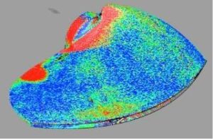
Structural Inspection – To make sure that the printed part is free from surface cracks or porosity. Tests such as Dye Penetrant Inspection, Ultrasonic Testing and CT Scanning are carried out.
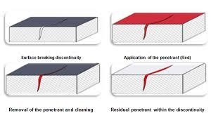
1. Dye Penetrant Inspection
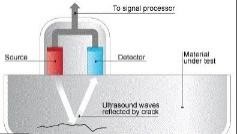
2. Ultrasonic Testing
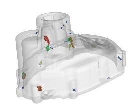
3. CT Scanning
Conclusion
By now, it is evident that a lot of processes go into obtaining the final functional part. Although it is to be noted that not all processes are required for every 3D printed part. It completely depends on the end application. At Rapid DMLS, we study your part and end requirement thoroughly and guide you through the entire 3D printing process from pre-processing to post-processing.