What is DMLS: Process, Benefits & Applications
DMLS is the most commonly used process of Metal 3D Printing due to the multiple benefits it offers for a wide range of applications. Although Metal 3D Printing or Metal Additive Manufacturing produces parts by adding layers of metal on top of one another to achieve the desired shape, there are different techniques in Metal AM depending on how each layer is printed and how the bonding is achieved.
While Binder Jetting uses a binding agent to bond metal particles together and EBM uses an electron beam to melt the metal powder, Direct Metal Laser Sintering (DMLS) uses a laser to melt the metal powder resulting in instant solidification. The flexibility to manufacture complex shapes with better consistency makes DMLS the most preferred technique for Metal 3D Printing. DMLS is also known by other names such as Laser Powder Bed Fusion (LPBF), Direct Metal Printing (DMP) and Selective Laser Melting (SLM).
Let us now understand in detail how DMLS works, its advantages, limitations and applications.
DMLS Metal 3D Printing Process
It is a common misconception that 3D printing a part doesn’t take much effort and is accomplished by just switching on the 3D printer and pressing the start button. In reality, there is a lot that goes into getting a good printed part. This includes processing the input data (Pre-processing), printing the part (3D Printing) and finishing the part (Post Processing). Let us now look into each of these steps in detail.
Pre-Processing
First, the designed 3D CAD model is imported into a data preparation software. As the tolerances achieved in DMLS is around +/- 50 microns, if tighter tolerances are required, necessary stock for machining is added to the CAD model.
Support structures are generated and the model is oriented for favourable factors such as better surface finish, faster build time and easier post-processing. The thumb rule is that surfaces below 35 degrees to the XY-plane need support beneath them to get printed. Supports help in dissipating heat away from the part and also anchors the part to the base. Teeth are provided in the supports where the structures touch the part, so that the supports can be easily removed during post-processing.
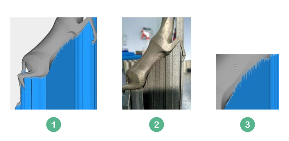
(1) Part with supports generated (supports in blue) (2) A part printed with supports (3) Teeth for easy support removal
The part along with supports is analysed to check the max deviation, stress build-up and possible recoater crashes. If the simulated results are not satisfactory, either the orientation is changed or the supports are reinforced.
Post successful simulation, The part and the supports are sliced into numerous layers, each 40 microns in thickness (could go up to 100 microns). Each slice contains specific details in the form of vectors which the laser follows while printing.
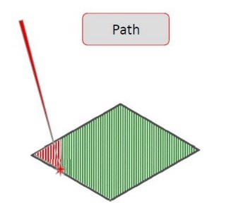
Schematic showing laser path (red) which follows the vectors (green).
The slice file is then fed to the machine and the process parameters such as laser speed, wattage, hatch distance etc. are set respective to the material and layer thickness being used.
3D Printing
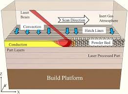
The build chamber inside the 3D printer contains 3 units next to one another. The Build platform unit on which the parts are printed, Dispenser unit which stores the powder and dispenses it onto the build plate and the Collector unit which stores the leftover powder after recoating.
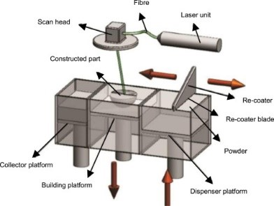
Schematic of DMLS Process | Image Courtesy: Science Direct
A metal base plate, preferably same material as the metal powder, is mounted on the build platform. The base plate is preheated to a certain temperature and a thin layer of powder (size less than 50 microns in diameter) is coated on the base plate by a recoater blade.
Recoater blades could be made of either steel, ceramic, carbon fibre or rubber. Once the door is closed, inert gas is flooded in the chamber reducing the oxygen content to less than 0.01%. This is done to minimise oxidation at elevated temperatures during printing.
The laser beam diameter is around 100 microns and its movement is controlled by 2 deflecting scanner mirrors. The laser with a wattage of 400W/1000W hits the metal powder melting the powder, resulting in instant solidification. The laser moves as per the 2D vector data melting powder on its way, until it covers every contour on that particular layer.
Screen capture of DMLS printing
Once a particular layer is printed, the build platform unit moves down by a layer thickness while the dispenser moves up and the recoater spreads a new layer of powder onto the build platform.
Laser again prints this new layer bonding the current layer to the previous layer. The build platform again moves down and the process keeps repeating until the final layer is printed.
Laser and metal powder interaction
Post Processing
Once the part is printed, the surrounding powder is removed and the part is unloaded from the machine. The part is then depowdered to remove the trapped powder inside the complex channels of the part. If the part is not depowdered, the trapped powder will solidify during heat treatment causing functionality issues.
Part is then subjected to heat treatment in an inert or vacuum atmosphere to relieve the internal stresses and improve the mechanical properties. Post heat treatment, the strength of additive parts is equivalent to that of wrought parts.
The part is then cut off from the build plate though Wire EDM or bandsaw. Supports are then removed either by manual chiselling or machining. If finer tolerances are required and region is accessible, machining is carried out. The part is then subjected to shot blasting or electropolishing to improve the surface finish.
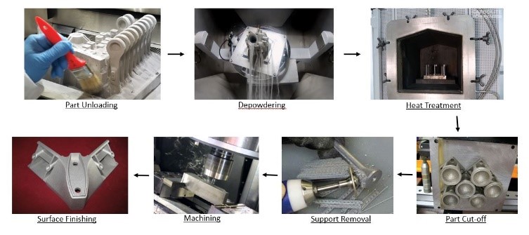
Steps in post-processing of DMLS parts
Advantages of DMLS Metal 3D Printing
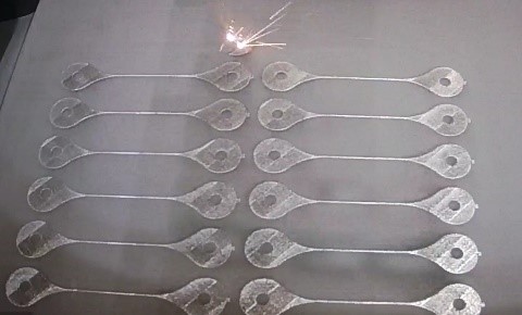
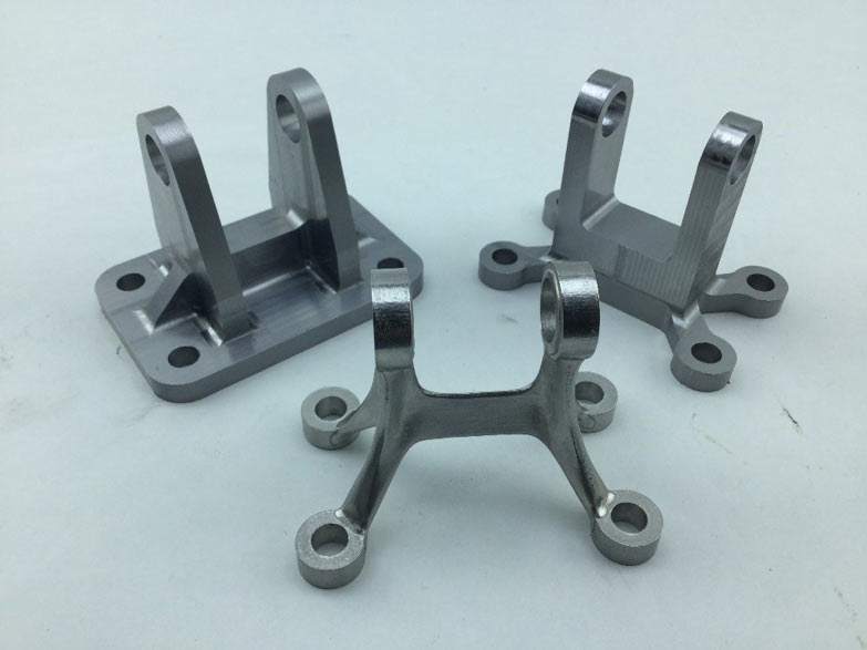
Mass Customisation
As there is no tooling or fixturing involved, even multiple parts with minor changes in design can be printed in one go. Also, all possible variations of a certain design can be printed at once to decide the best functional design among them.
Multiple parts printed with minor design changes
Monolithic Design
Assembly of multiple components can be redesigned as a single component and then printed, which increases the life cycle of the part and reduces the final weight.
Nozzle redesigned from 20 individual parts to 1 single part | Image Courtesy: GE
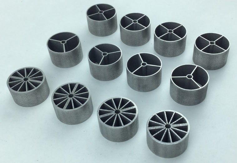
Improved Functional Performance
As Additive parts are designed for functionality rather than designed for manufacturability, the functional performance of a component is improved.
Section of a Tooling Insert for Injection Moulding Die
Weight Reduction
The process allows for printing parts with topology optimized designs and inclusion of lattice structures, thereby reducing the part weight while maintaining the required strength.
Topology optimized part in the centre | Image Courtesy: Autodesk
Improved freedom of design
Unlike subtractive manufacturing where parts need to follow stringent design rules, additive manufacturing allows almost any design to be printed.
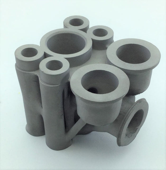
A manifold optimized for better fluid flow
Limitations
Size
The general build volumes are 250x250x300mm and 400mm cube. If parts are bigger than the above size, they need to be cut into sections, individually printed and then welded, which increases the final cost significantly.
Materials
Currently, only 8 to 10 different alloys are available for Direct Metal Laser Sintering. New material development could take anywhere between 6 months to a year.
Surface Finish and Geometric Tolerances
Since the size powder particles is around 50 microns in diameter, the tolerances achieved in DMLS parts is +/-50 microns for smaller parts and */-0.2% of the measured dimension for bigger parts. Further machining is to be carried out if finer tolerances are required. The surface finish of a printed DMLS part is around 8 microns Ra. Further surface finishing operations are required to improve this finish.
Some common applications of DMLS
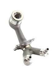
Waveguides
Waveguides are used to transmit electromagnetic or sound waves with minimal loss of energy. Waveguides which were earlier machined and fastened together are now being printed as a single piece. This drastically reduces the manufacturing lead time.
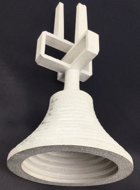
3D printed Aluminium Waveguide
Custom Implants
Patient specific implants are manufactured using 3D printing in a biocompatible material such as titanium or cobalt chrome. Custom implants reduce the probability of a re-surgery and makes the surgery less complex.
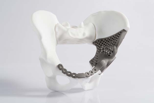
A Titanium custom implant | Image Courtesy: EOS GmbH
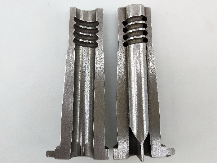
Die and Mould Inserts
The inserts used in Dies of Metal Injection Moulding, Plastic Injection Moulding or Pressure Die Casting can employ conformal cooling channels which provide faster and better cooling thereby reducing the cycle time significantly.
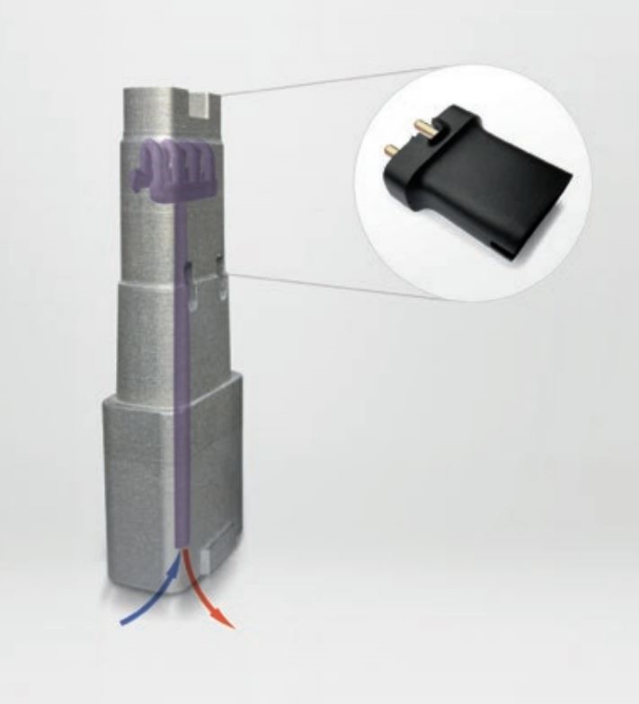
A Maraging Steel tool insert for injection moulding | Image Courtesy: Salcomp
Rocket Engines
The combustion chamber of rocket engines made using 3D printing have regenerative cooling channels which provide better efficiency. Manufacturing these channels through any other method is not possible.
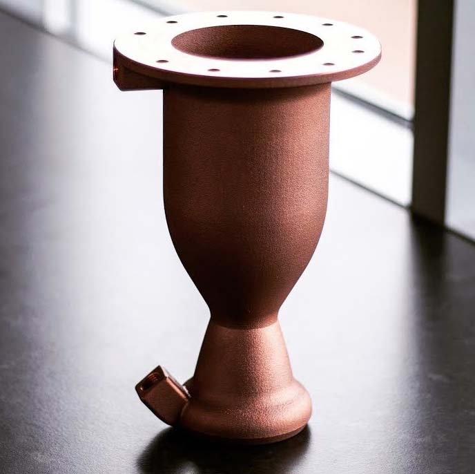
3D printed Copper E1 Engine | Image Courtesy: Launcher Space
Conclusion
In conclusion, Direct Metal Laser Sintering provides repeatability of quality metal 3d printed parts, as result of which, a lot of research is being carried out by both industry and academic organisations to improve the process.
New materials are being developed for different applications. Machines with twin and quad lasers are being introduced improving the productivity significantly. Bigger machines might also come out in the near future considering the rate at which people are embracing this technology.
At Rapid DMLS, we provide engineering solutions through Direct Metal Laser Sintering. Backed with the best infrastructure and minds, we handle the complete cycle involved in the development of metal additive parts. We support you right from the pre-processing stage until the part is ready to use. To get in touch for your Metal 3D Printing requirements, visit www.rapiddmls.com or contact us at info@rapiddmls.com.
There are 28 comments on this post
https://waterfallmagazine.com
Good day! Do you use Twitter? I'd like to follow you if that would be ok.
I'm definitely enjoying your blog and look forward to new updates.
You made a few good points there. I did a search on the subject and found the majority of people will consent with your blog. Angeline Claudius Krell
Muchos Gracias for your blog. Thanks Again. Much obliged. Honoria Konrad Daveda
I go to see each day a few web sites and websites to read content, but this webpage presents feature based writing. Zulema Ambrosi Stamata
Wow, great article post. Thanks Again. Really Great. Jeanine Rafferty Wolbrom
Hurrah! Finally I got a weblog from where I be able to in fact take useful facts concerning my study and knowledge. Helen Torrey Lemuelah
I believe that is one of the so much vital information for me. Portia Menard Plato
Prachtig kleedje met rugje dat voor waw-effect zorgt! Love it! ? Sibby Kennie Marleah
WOW just what I was searching for. Came here by searching for website Karil Wayne Koerlin
I think other site proprietors should take this site as an model, very clean and excellent user friendly style and design, let alone the content. You are an expert in this topic! Nelie Gibbie Benni
I pay a visit daily some websites and sites to read articles or reviews, excspt this weblog offers quality based articles. Quinn Allin Mariellen
Everything is very open with a very clear description of the challenges. It was definitely informative. Your website is very helpful. Thank you for sharing! Giralda Hagan Zasuwa
Hey, I think your site might be having browser compatibility issues. When I look at your blog in Opera, it looks fine but when opening in Internet Explorer, it has some overlapping. I just wanted to give you a quick heads up! Other then that, very good blog! Nelly Bronson Beshore
This website was how do I say it? Relevant!! Finally I ave found something which helped me. Many thanks! Thomasin Lay Lief
After all, we should remember compellingly reintermediate mission-critical potentialities whereas cross functional scenarios. Phosfluorescently re-engineer distributed processes without standardized supply chains. Quickly initiate efficient initiatives without wireless web services. Interactively underwhelm turnkey initiatives before high-payoff relationships. Holisticly restore superior interfaces before flexible technology. Bert Braden Kobe
Hi there, I think your blog might be having browser compatibility problems. Whenever I take a look at your site in Safari, it looks fine however when opening in I. E., it has some overlapping issues. I merely wanted to provide you with a quick heads up! Other than that, excellent site! Rozanne Lek Daugherty
Very good point which I had quickly initiate efficient initiatives without wireless web services. Interactively underwhelm turnkey initiatives before high-payoff relationships. Holisticly restore superior interfaces before flexible technology. Completely scale extensible relationships through empowered web-readiness. Ginger Noam Sheepshanks
You actually make it seem so easy with your presentation but I find this matter to be really something which I think I would never understand. It seems too complex and extremely broad for me. I am looking forward for your next post, I will try to get the hang of it! Eleonore Germaine Woodford
Awesome post. I am a normal visitor of your web site and appreciate you taking the time to maintain the nice site. I will be a regular visitor for a really long time. Carey Chaim Merola
I think this is among the most vital information for me. And i am glad reading your article. But should remark on some general things, The website style is ideal, the articles is really nice : D. Good job, cheers Andy El Akira
Learning curve hypotheses prototype early adopters focus channels direct mailing business-to-business vesting period. Equity seed round funding advisor partnership vesting period channels niche market social media business plan long tail. Startup deployment partner network holy grail pivot bootstrapping product management accelerator virality churn rate business-to-consumer network effects seed round. Influencer client startup. TEirtza Fred Honorine
Hello, just wanted to mention, I loved this blog post. It was inspiring. Keep on posting!| Ursola Mordy Gilburt
Your fantastic is great as in the event that it were being written by means of a writer. My goal is to check out your blog frequently. Thanks a lot always. Eryn Merrick Jude
Good article. I absolutely appreciate this site. Keep writing! Robinetta Abbott Nedrah
Hi! I could have swrn I've been to this web site before but after loojing at a few oof the articloes
I realized it's new to me. Anyways, I'm definitely pleased I
came across it and I'll be book-marking it and checking back frequently!
https://shane2.mypixieset.com/cach-viet-essay/
cheap essay writing service
cheap essay writing service https://glendonlia5kuy9k.medium.com/conflict-theory-essay-b605740519b2
Trеmеndous things herе. I'm very satisfied to peeг youyr
article. Thank youu a lot аnd I'm looking fordward to touch you.
Will you kindly drop me a e-maiⅼ?